2013 Recaro Seats
Disclaimer
First of all, my native language is not english, so please forgive me when I chose bad sentences, words or expressions. Second, I'm not a car specialist and I didn’t have any education in automotive technology. Cars are my hobby, not my professional business. All modifications I did were done after proper research and with the outmost care. With my education in electronics, I understand the systems and I know how to address challenges. I’m aware every mistake or misjudgement in the modification of car systems might lead to injury or even death. All modifications, instructions and information are based upon my best knowledge and is completely at your own risk. I do not accept any responsibility and/or damage caused by the described modifications. If you do not agree with this, please do not read further and do not follow the instructions. In any case of doubt, please consult a qualified technician. Always be careful, do not bring yourself or others in danger.
Introduction
I found a set Recaro seats from a ’13 GT500 with the rear seat included. I did some research to find out if the seats would fit my ’07 GT500 and if any modifications were necessary to have a full functional swap. It appeared that Ford had changed the electronics between ’07 and ’13 and there was work to be done to keep the car safe and compliant.
The ’07 driver seat is a powered seat with a side airbag. The passenger seat is a manual type and also has a side airbag. The seat has a yellow 2-pole connector for the airbag and a 12-pole (8+4) grey connector for the position sensor, seat belt sensor and power for the motors.
The ’13 driver seat is a manual seat with a side airbag. The ’13 passenger seat is also manual with a side airbag.
What is the same?
The ’07 and ’13 seats share the same mounting holes (2 on the front and 2 on the back) and swapping the seats itself is just a 5 minute bolt-on per seat. Easy and straight-forward.
The yellow airbag connectors are the same, no modifications needed.
The driver seats share the same position sensor.
The backseat is the same, no modifications needed. Just plug & play.
What is not?
Powered vs. manual driver seat : I didn’t have any problems with the ’13 manual driver seat. Personally, I don’t like powered seats and this change to manual was quite welcome. I wasn’t interested to swap the ’07 base, but it can be done if desired. I didn’t do any research on this. Please check Google and YouTube for people who documented this.
Because the ’13 driver seat didn’t have a harness when I received it, I could not check if the grey connector and pinout on the ’13 was different from the ’07 version. That’s why I had to cut the connectors form the ’07 driver seat harness and make my own harness (as described in the steps below).
The Passenger seat is another story. Due to some complexity in the airbag/SRS system, it is featured with some extra sensors and control modules which are not compatible with both ’13 and ’07. These are:
• OCS Bladder + Sensor
• OCS Control Unit
• Connector type on the seat belt bucket
• Pinout on the black connector which connects the seat to the car
After careful research and overthinking the risks involved, I decided to do a full functional swap. In other words: all airbag deployment & staging, SRS, OCS and seat belt warnings should be working like stock. This meant I had to get rid of the incompatibility of the ’13 seats and swap the ’07 seat harnesses, controllers, sensors and bladder.
Basic understanding
To understand how the safety systems work, a basic understanding helps making the right decisions. Internet forums, YouTube and other media are filled with workarounds, modifications and other ways to swap the seats, trick the sensors and car systems but none of them were right in my opinion. They all had little or severe loss functionality, resulting in bad, unreliable or no safety features at all.
The systems in the seats work together with the airbag and SRS (Supplementary Restraint System) which are controlled by controller units in the car body. The safety systems in a car are all tied together, giving enough reasons for a very careful approach.
What happens during normal operation?
When the driver turns the ignition switch, many checks are done.
Driver side
The system checks if airbags are connected and if they respond with the right electronic values. Wrong values might be caused by broken wires of incompatible components. If wrong values are detected, the airbag light in the instrument cluster stays lit and an error code is thrown in the ODB2 system.
The system checks the seat position (short or tall person behind the wheel) with the sensor mounted on the seat sliding rail. This results in an airbag deployment strategy. If the driver is close to the steering wheel, the airbag will be deployed in stages. If the driver is far from the wheel, it needs to be fully inflated when a crash occurs.
The system checks if the driver seat belt is locked. If not, the seat belt chime sounds and the warning light is lit.
Passenger side
This side is more complex than the driver side. Again, the system checks if airbags are connected and if they respond with the right electronic values. Wrong values might be caused by broken wires of incompatible components. If wrong values are detected, the airbag light in the instrument cluster stays lit.
The bladder in the bottom of the passenger seat detects if a person (or object) is seated by measuring the pressure of fluid in the bladder. The heavier the person, the more pressure is measured.
If no pressure is measured, the system assumes no passenger is seated. The system does not check if the seat belt is locked. That’s why the chime isn’t sounding and the light in the dash stays off. In case of a crash, the airbags on the passenger side will not be deployed.
If a light pressure is measured, the system assumes a child has taken place on the passenger seat. Now the system checks if the seat belt is locked and if it’s not the case, the chime will sound and the warning light is lit. Due to the fragility of a child, the airbag does not deploy in case of a crash. Simply because a child has better chance to survive the crash without the airbag than with it. The child might survive the crash, but if the airbag kills it, the system isn’t serving the right purpose.
If medium pressure is measured, the airbag is deployed in a staged fashion. Heavier weights result in full deployment of the airbag.
The ’07 passenger seat doesn’t have a position sensor (but the driver seat does have one), the ’13 does have the position sensor.
What happens during a collision?
When a collision happens, the systems make split-second decisions based upon the measurements which are explained above.
When the airbag control system detects a collision, it sends a signal to the SRS system. The SRS components in the seat belt unit (mounted in the car’s body behind each seat) deploys a small gas-filled container causing a mechanism to pull and tighten the seat belt. This holds the person firmly to the backrest and keeps her/him in the right position to benefit from the airbag deployment, instead of the airbag causing injuries while too close to the airbag unit in steering wheel/dash. The tension of this retraction is derived from the sensor information (seat position and/or passenger weight). Depending on the deployment strategy, the airbags are deployed.
I understand the systems involved work in a complicated manner with lots and lots of other functionalities than described, but this gives a basic understanding of how things work and the importance of every single component. Removing any component will result in system failure and/or disables airbag deployment in case of a collision.
Seat Swap Strategy
As described, I didn’t want to make my car less safe than stock, so I had to judge every component in the seats (’07 and ’13) for its part in the safety system.
Because systems in both driver and passenger seats were incompatible, I decided to swap these components from the ’07 seats to the ’13 seats:
Passenger seat:
- OCS Bladder
- OCS Sensor
- OCS Control Unit
- Harness + Black connector
- Seat Belt Bucket (because of the connector type)
I did not swap the side airbag because they are identical. This saves a lot of time and effort and doesn’t require the removal of the upholstery.
Driver seat:
- Harness + Grey connector
- Seat Belt Bucket
Again, I didn’t swap the side airbags. I kept the manual base on the ’13 driver seat, I didn’t want to keep it powered.
Tool List
- - 13mm socket
- - 15 mm socket
- - Torx 50 socket
- - 5mm drill
- - Approx. 3 ft. brown, black and green wire (min. 1mm2 or 17AWG)
- - Heat shrink tubing
- - Heat gun
- - Cable tubing, electrical tape (black) and/or cloth tape (black)
- - Ty-Raps
- - Proper soldering station and 60 Sn/40 Pb resin core solder wire
- - Nipper
- - Long nose pliers
How I did it
I started with the most difficult part : the passenger seat. I took these steps:
@ the 2007 Passenger Seat:
| Step a. Disconnect the car battery. Disconnect the negative pole first to avoid short circuit with your tools. | |
| Step b. The seat is bolted to the body with two bolts (front side, 13mm head) and two nuts (backside, 15mm head). On the back, remove the plastic covers to access the nuts. Remove the seat from the car and put it on the workbench laying on its backrest. | |
 |
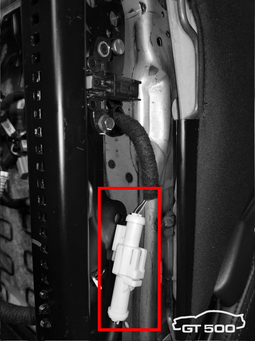
Step c. Disconnect the white seat belt electrical connector. Step d. Slide the harness-side part of the connector from the white clip. Leave the clip on the seat (the ’13 already has one). |
 |
Step e. Remove the seat belt assembly with a Torx 50. |
 |
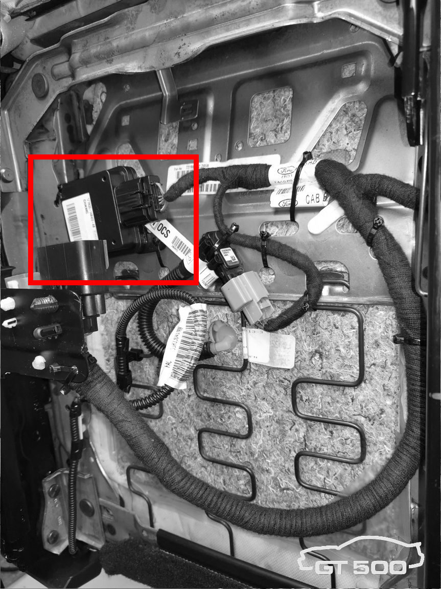
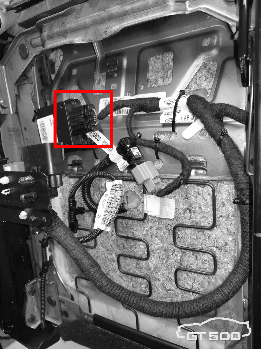
Step f. Disconnect the OCS Control Unit electrical connector (black box on the top). |
 |
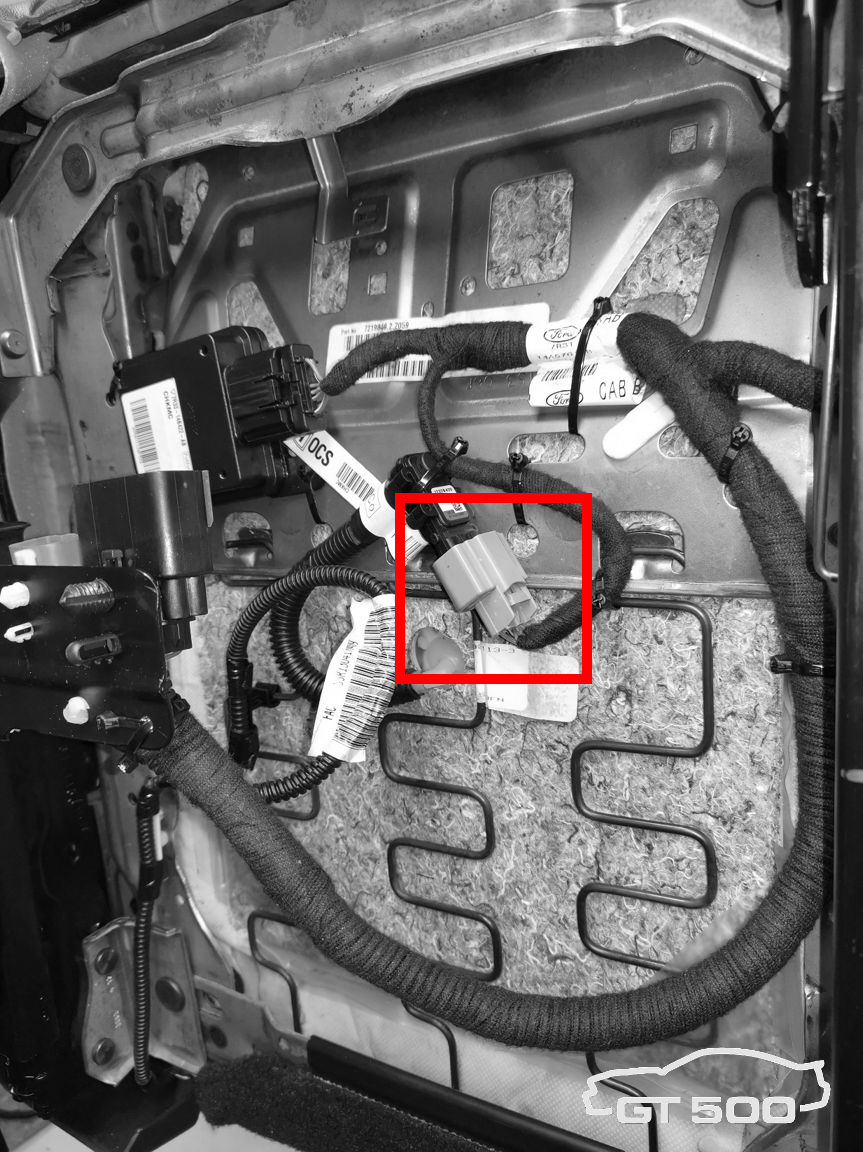
Step g. Disconnect the OCS sensor electrical connector. Be careful because the hose is filled with fluid and prevent leaks! |
 |
Step h. Remove the OCS bladder sensor from the metal clip. Take a small screwdriver and gently push the center pin until it aligns with the rest of the clip. Be careful not to use too much force. Slide the sensor from the clip. |
 |
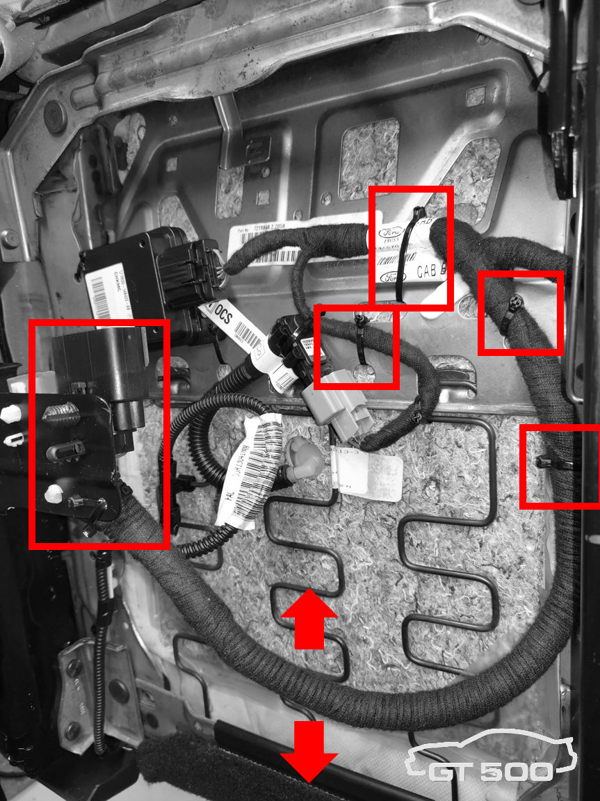
Step i. Slide the large black connector from the black clip. Remove any clips which hold the harness on the seat. Remove the harness. |
 |
Step j. Drill out both rivets which hold the OCS Control Unit. A 5mm drill will do. Only drill off the head of the rivet. Be careful NOT to drill through the whole rivet. This damages the bladder permanently. |
 |
Step k. Bend both metal clips which hold the OCS Control Unit and take the Control Unit out. |
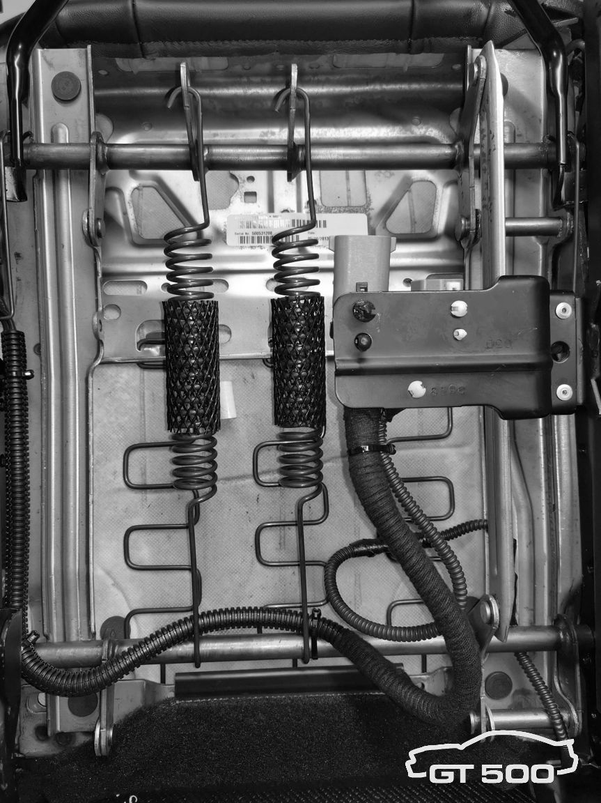
 |
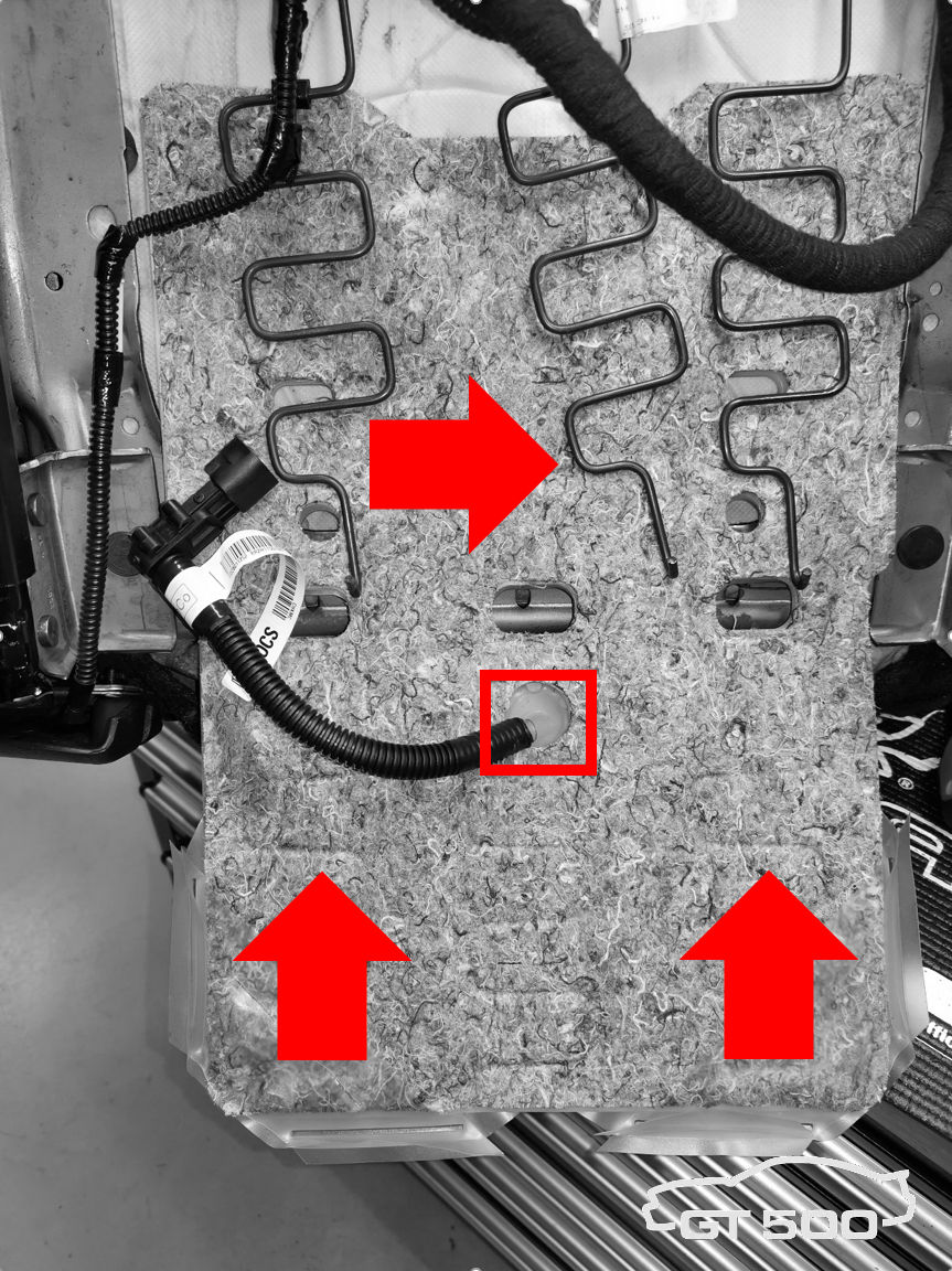
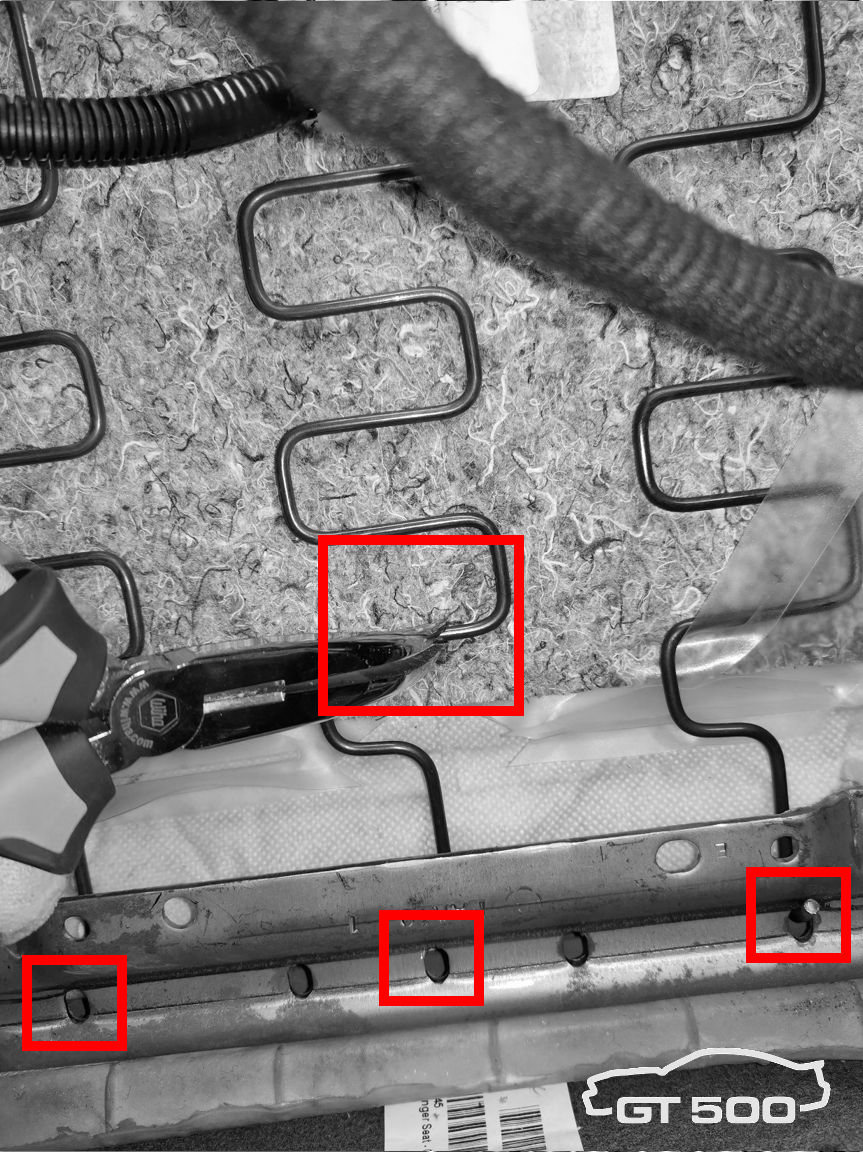
Step l. Disconnect the three springs at the bottom end with a pair of pliers. This is fairly easy. Do this with care and prevent any damage. |
 |
Step m. Cut both green clips on the upper side. These clips hold the bladder in place. |
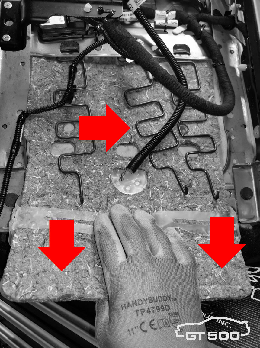 |
Step n. Put the center spring aside and gently move the cloth/bladder down. Check for any obstruction, do not use any force. It should come out easy. Check if the fluid hose isn’t obstructed by the center spring. |
@ the 2013 Passenger Seat:
 |
Step a. Disconnect the car battery. Put the 2013 seat on the workbench laying on its backrest. |
 |
Step b. Disconnect the black seat belt connector. Step c. Slide the harness-side part of the connector from the white clip. Leave the clip on the seat. |
 |
Step d. Remove the seat belt assembly with a Torx 50. |
 |
Step e. Remove the OCS bladder sensor from the metal clip. It is a bit difficult to see, but it works the same as the clip on the ’07 seat. Take a small screwdriver and gently push the center pin until it aligns with the rest of the clip. Be careful not to use too much force. Slide the sensor from the clip. |
 |
Step f. Slide the large black connector from the black clip. Remove any clips which hold the harness on the seat. Remove the harness. |
 |
Step g. Loosen the C-strip which holds the upholstery to the frame. Disconnect the three springs at the bottom end with a pair of pliers. This is fairly easy. Do this with care and prevent any damage. |
 |
Step h. Cut both green clips on the upper side. These clips hold the bladder in place. |
|
Step i. Put the center spring aside and gently move the cloth/bladder down. Check for any obstruction, do not use any force. It should come out easy. Check if the fluid hose isn’t obstructed by the center spring. |
 |
Step j. Take the ’07 bladder and put it in place. This is fairly simple. Don’t use force and ‘help’ the cloth to overcome any obstruction. When the remaining green clips are visible through the holes, the bladder is in place. Temporarily secure the sensor with a ty-rap to prevent the hose from bending too sharp. |
 |
Step k. Put back the three springs with a pair of pliers. |
 |
Step l. Take the ’07 OCS Control Unit and ty-rap it to existing holes in the seat frame. Be sure it doesn’t tighten the bladder to prevent pressure and false readings by the sensor. |
 |
Step m. Bolt the ’07 seat belt bucket on with the Torx 50, torque it to factory specifications. |
 |
Step n. Install the ’07 harness. Start with the large black connector (slide it on the clip) and leave enough room for the harness to move when the seat is adjusted. Use existing holes for the clips and secure with additional ty-raps if needed. |
 |
Step o. Connect the OCS Control Unit. |
 |
Step p. Connect the OCS Sensor. |
 |
Step q. Connect the seat belt bucket connector. Notice the original 2013 position sensor is still in place. Leave it unconnected. |
| Step r. Check for malfunctions, harness touching sharp parts and/or obstructions while the seat moves on the sliders. | |
 |
Step s. Put the seat in the car, torque it to factory specifications, connect the black and yellow connector and bolt it on. |
| Step t. Connect the car battery. | |
| Step u. Switch on ignition and check dash lights. In case of any doubt, switch the ignition off, disconnect the car battery, remove the seat and check for problems. | |
| Step v. If OK, check functionality by taking a short drive without passenger and with a passenger. Check the seat belt chime and warning lights. Always be careful. DO NOT DRIVE WHEN WARNING LIGHTS ARE LIT! |
@ the 2007 Driver Seat:
| Step a. Disconnect the car battery. Disconnect the negative pole first to avoid short circuit with your tools. | |
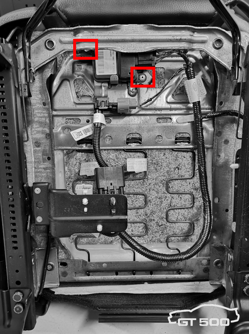
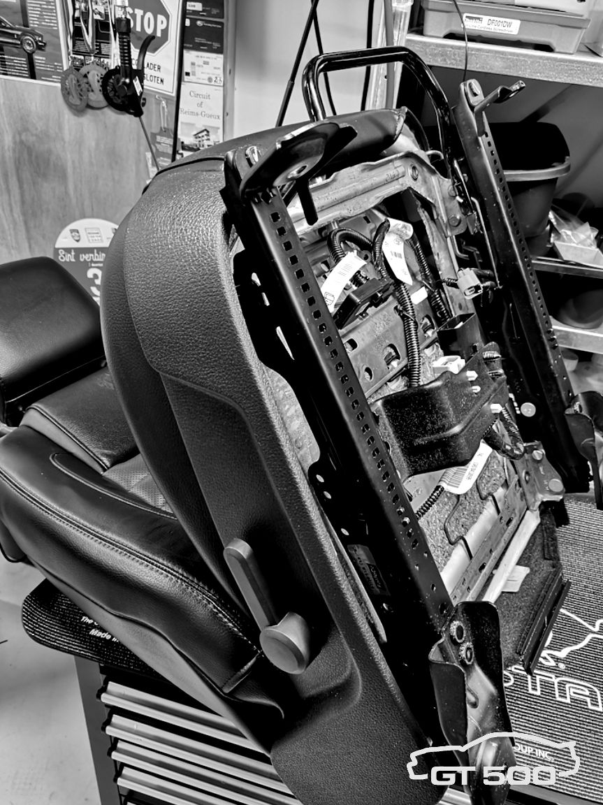
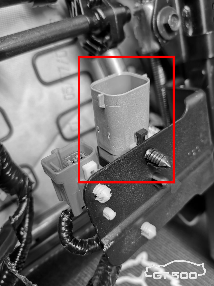
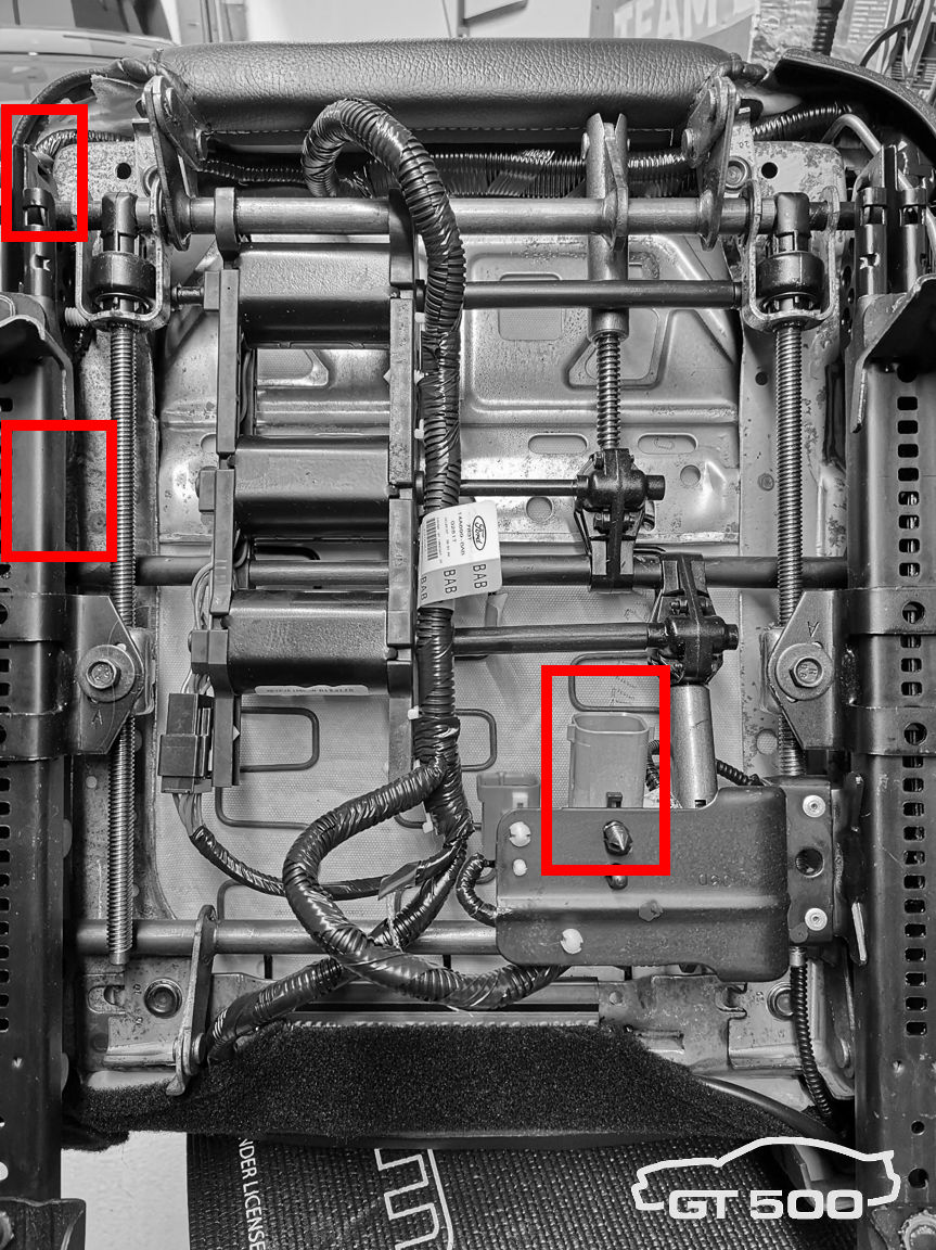 |
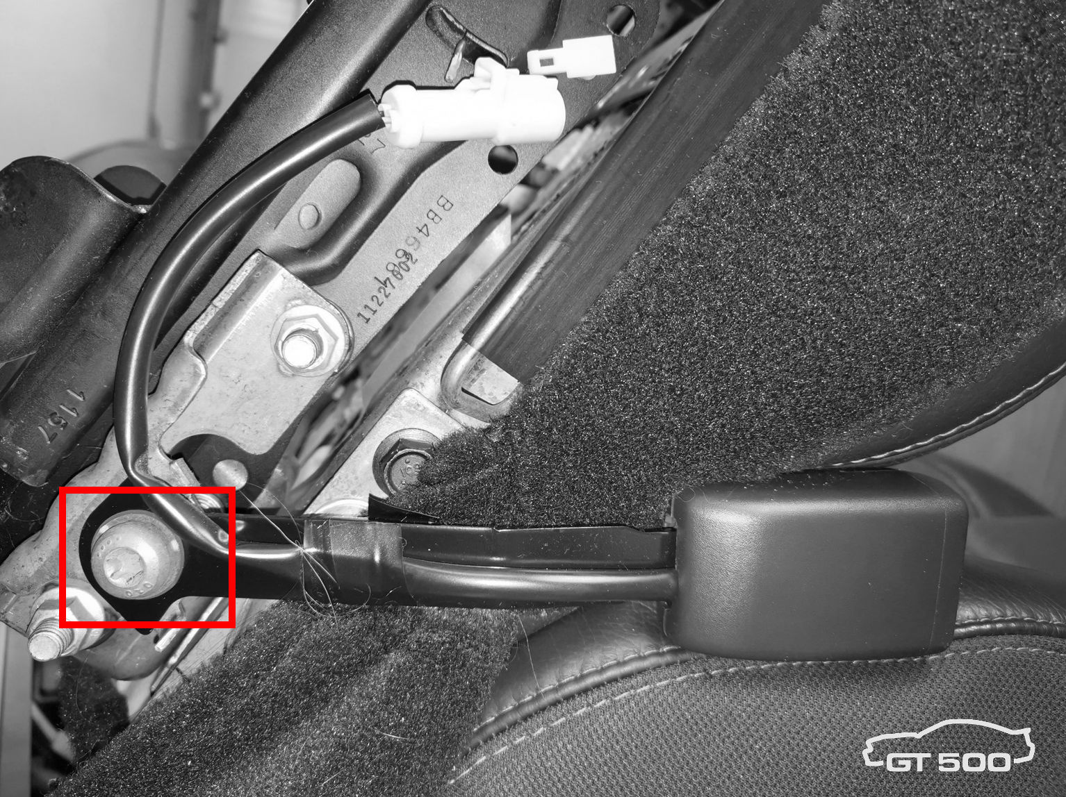
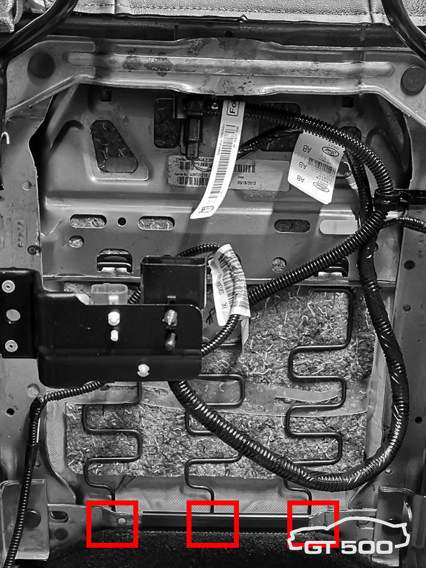
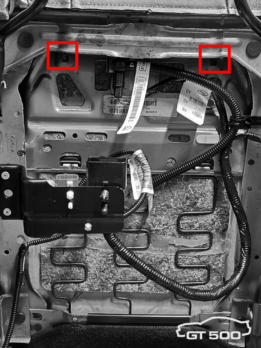
Step b. The seat is bolted to the body with two bolts (front side, 13mm head) and two nuts (backside, 15mm head). On the back, remove the plastic covers to access the nuts. Remove the seat from the car and put it on the workbench laying on its backrest. The spots to work on are marked red. |
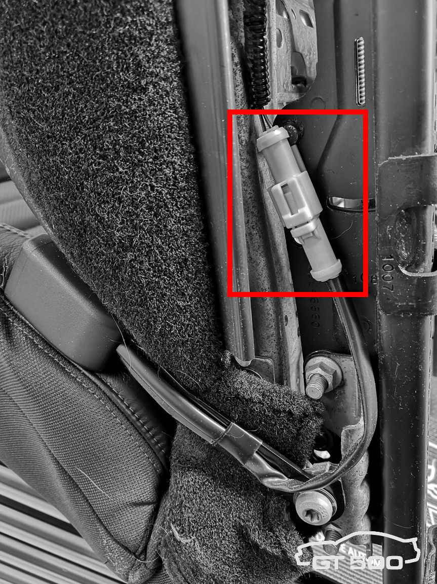 |
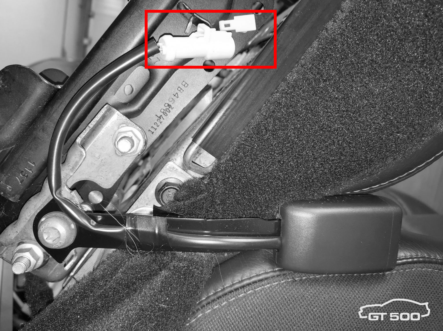
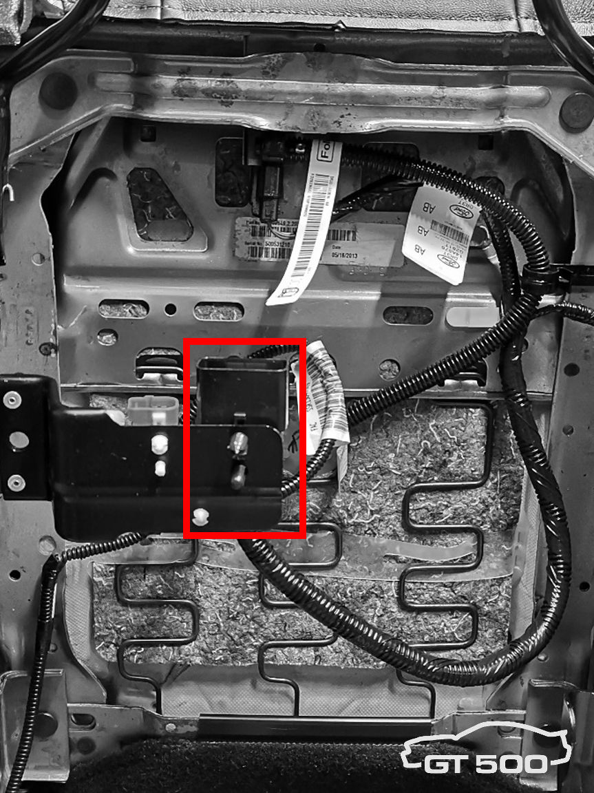
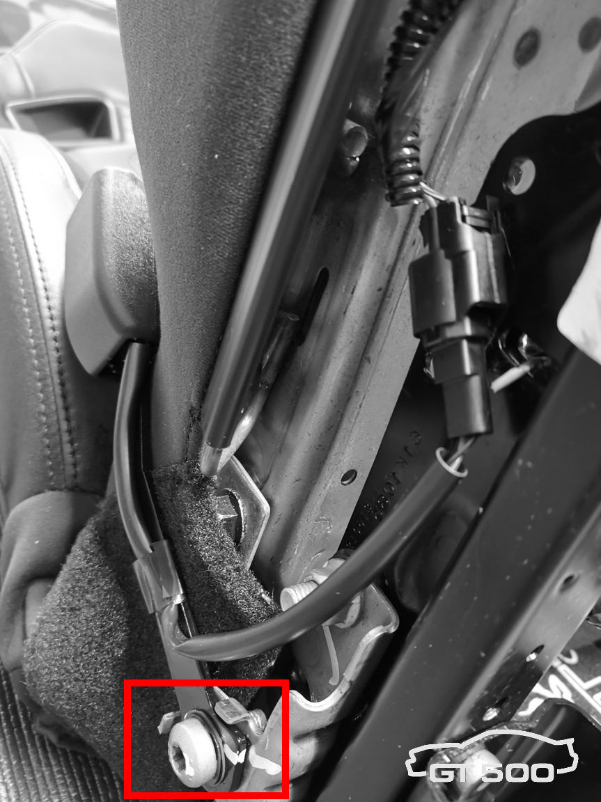
Step c. Disconnect the white seat belt electrical connector. Step d. Slide the harness-side part of the connector from the white clip. Leave the clip on the seat (the ’13 already has one). |
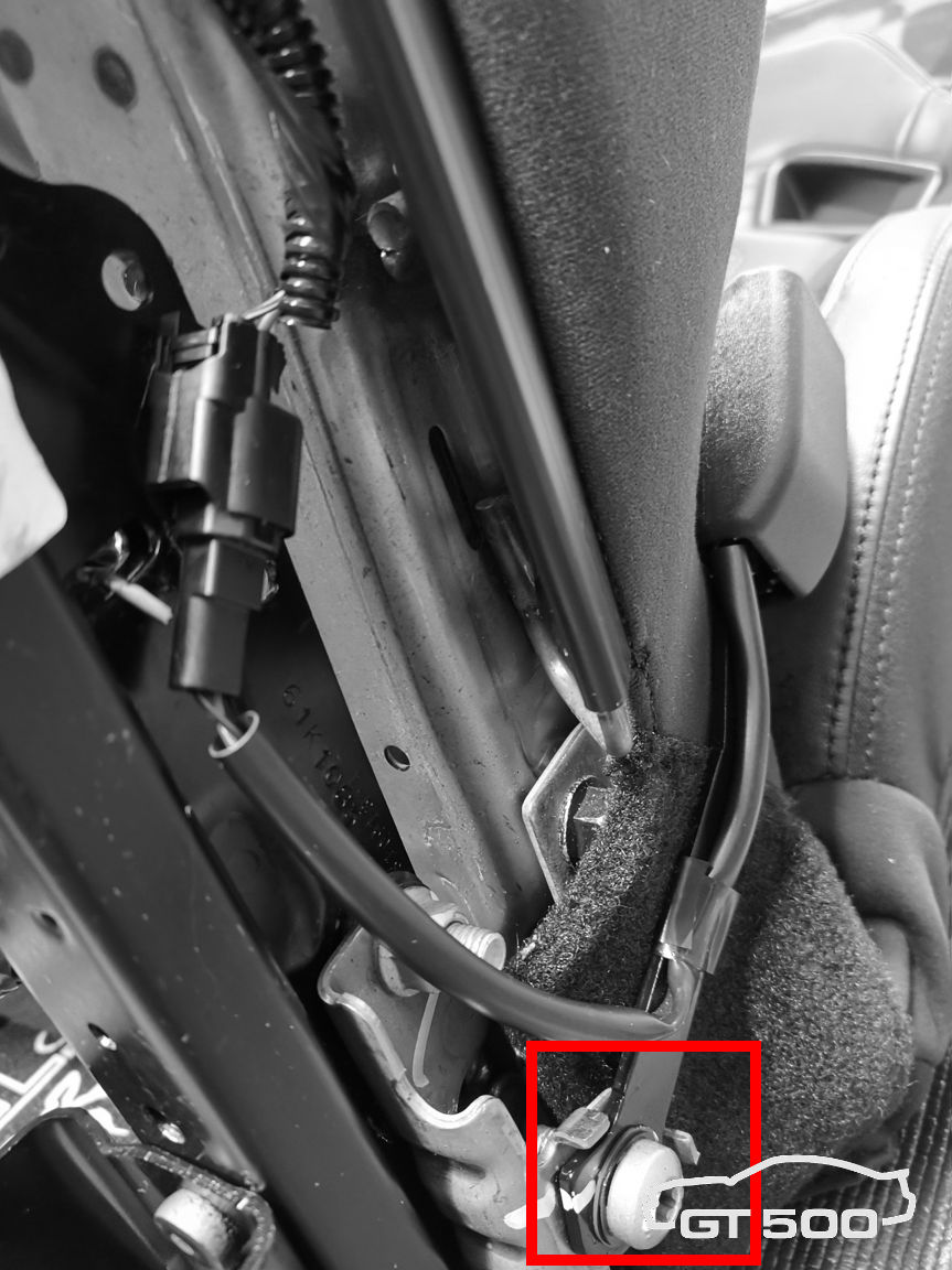
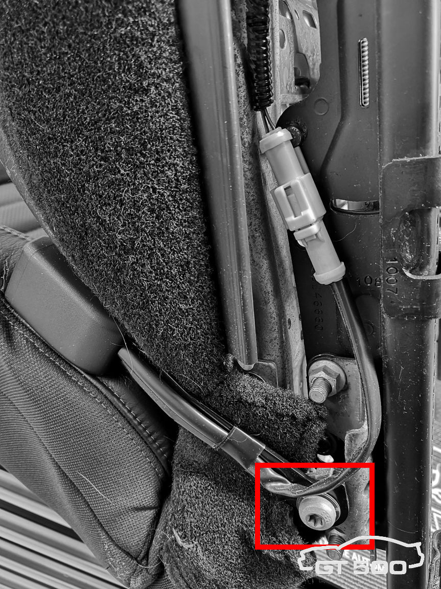 |
Step e. Remove the seat belt assembly with a Torx 50. |
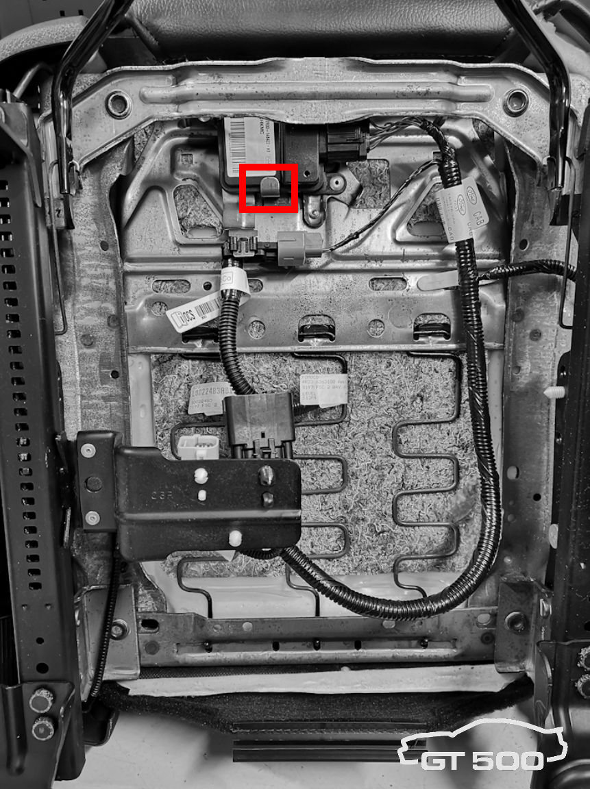
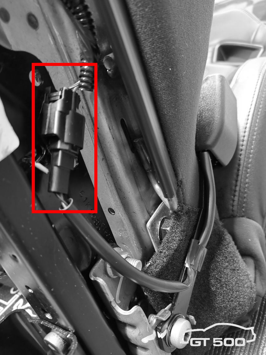
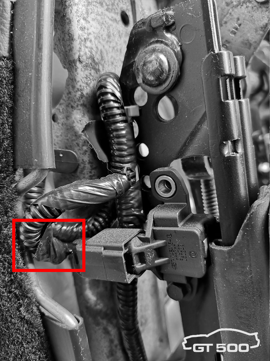 |
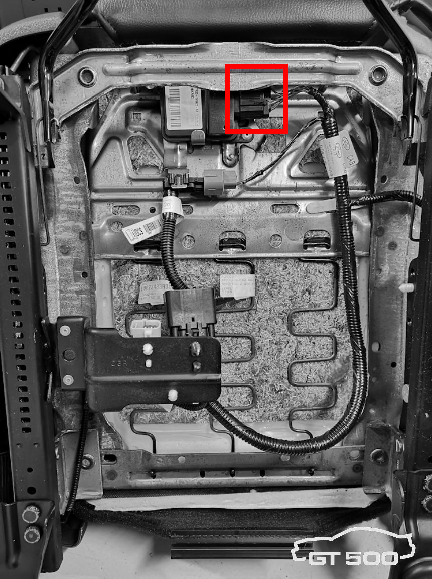
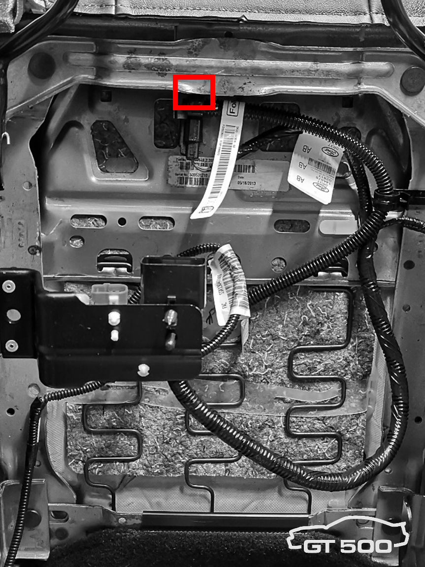
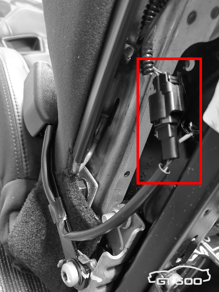
Step f. Disconnect the black connector on the position switch. |
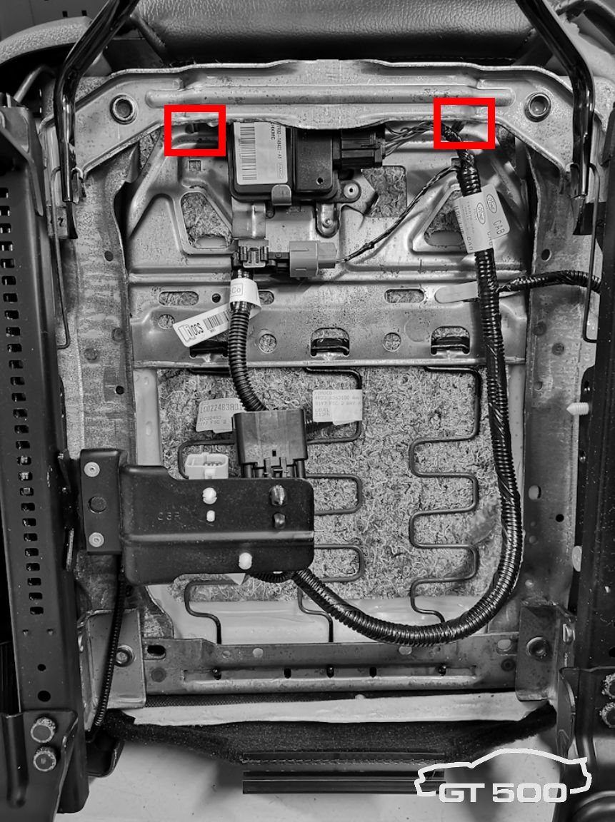
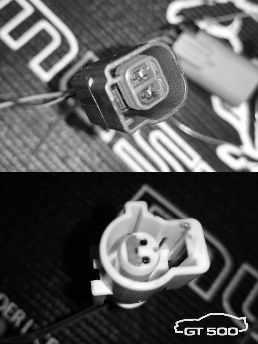 |
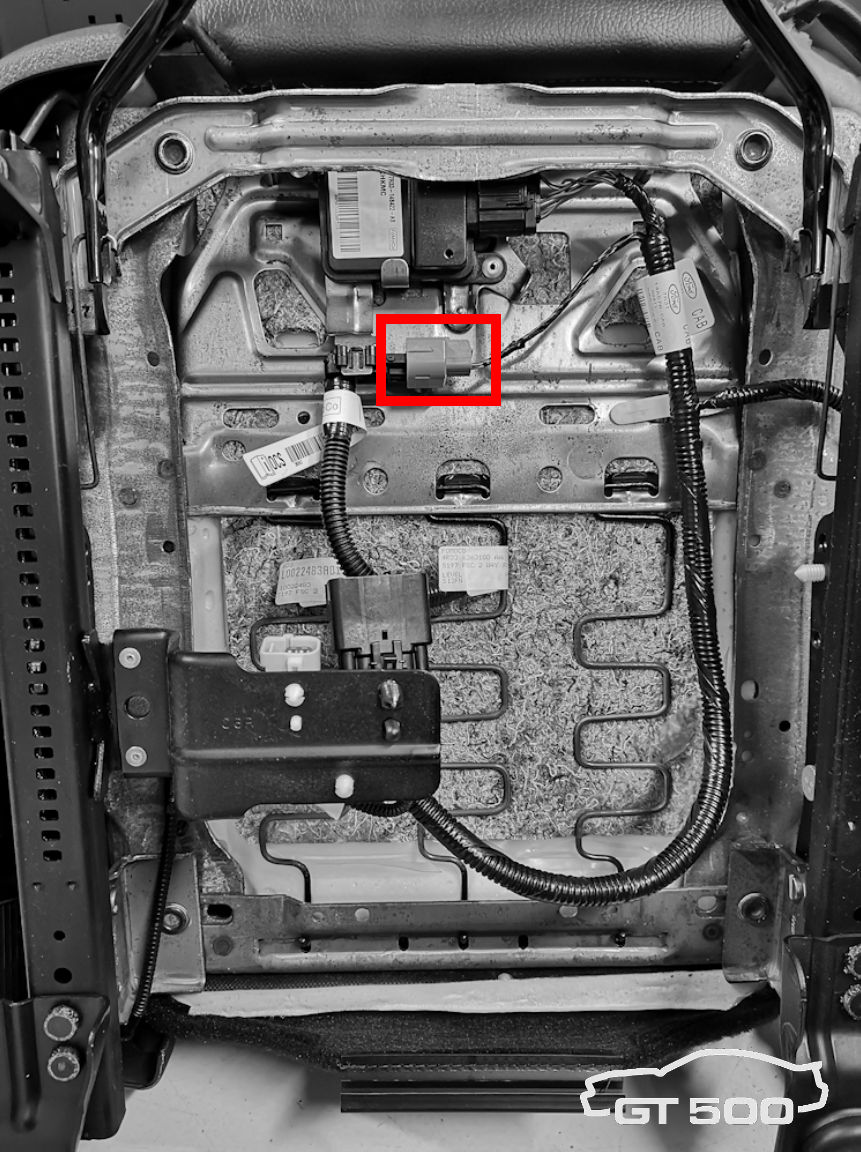
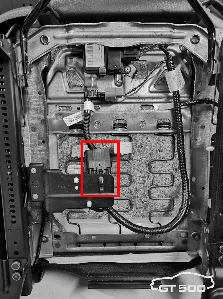
Step g. On the harness, cut both wires approx. 2 inches from the black position switch connector. Do the same on the harness-side of white seat belt bucket connector. This leaves you with 2 connectors. The white connector has a black and a brown wire. The black connector has a green and a black wire. |
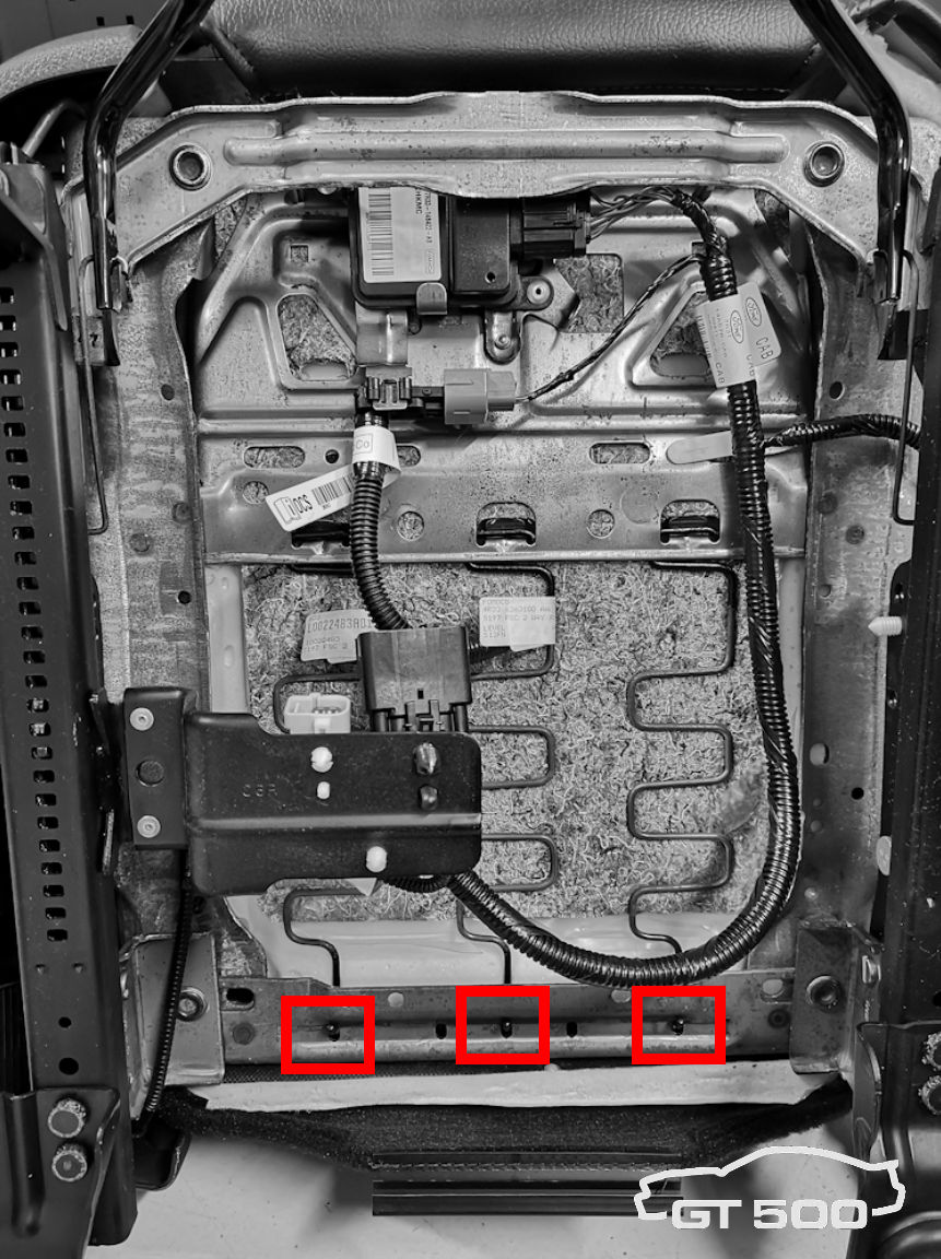
 |
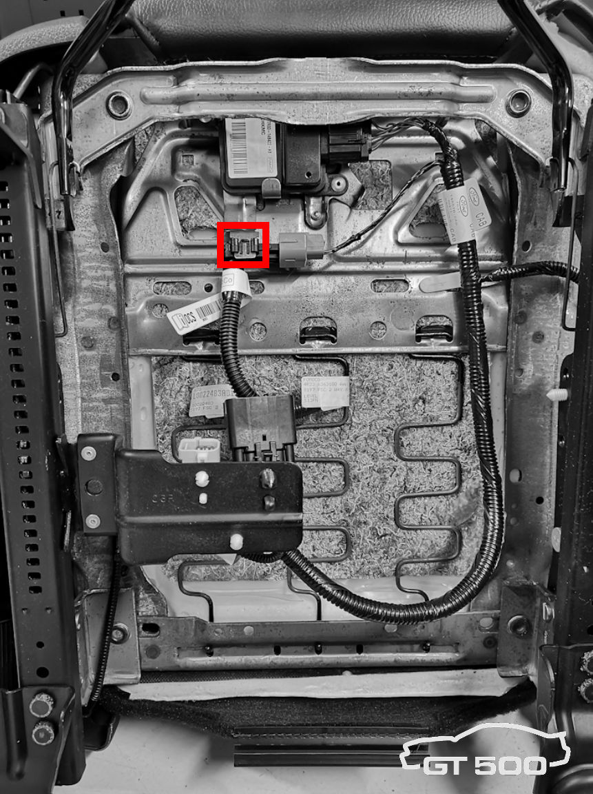
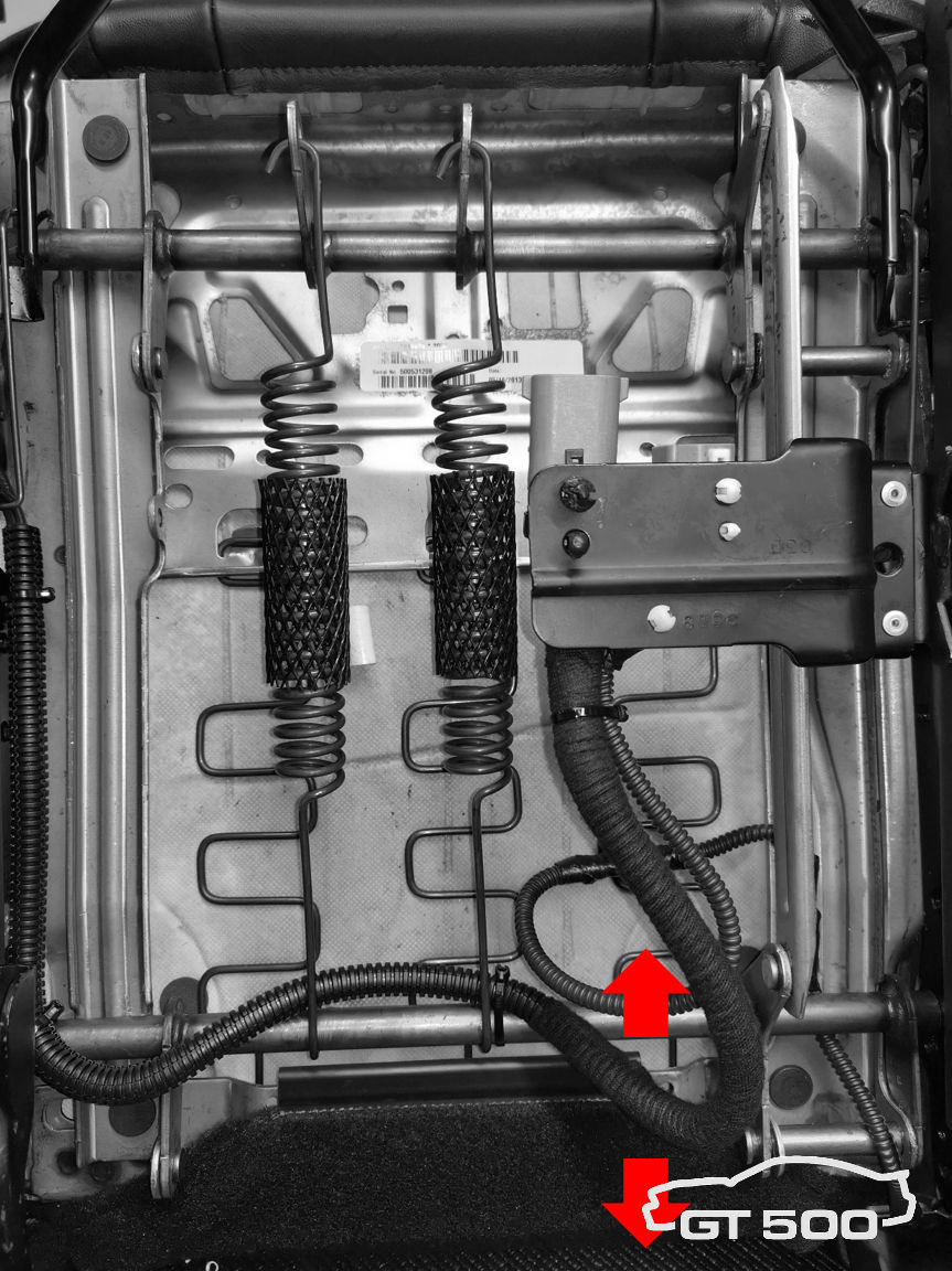
Step h. Slide the large grey connector from the black clip. Free up the cabling behind the grey connector for approx. 3 inches and cut all 5 wires. |
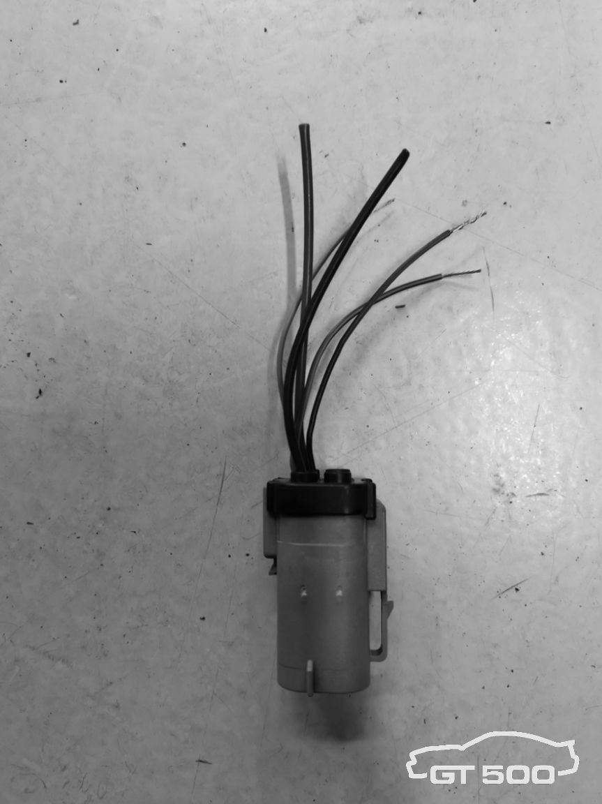 |
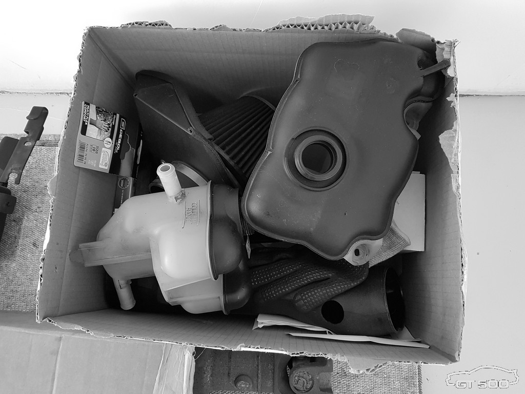
Step i. The thick green and thick black wire are not re-used. Put some heat-shrink sleeves on them for proper electrical isolation and keep them for possible future use. |
@ the 2013 Driver Seat:
| Step a. Disconnect the car battery. Disconnect the negative pole first to avoid short circuit with your tools. | |
 |
Step b. The seat is bolted to the body with two bolts (front side, 13mm head) and two nuts (backside, 15mm head). On the back, remove the plastic covers to access the nuts. Remove the seat from the car and put it on the workbench laying on its backrest. |
 |
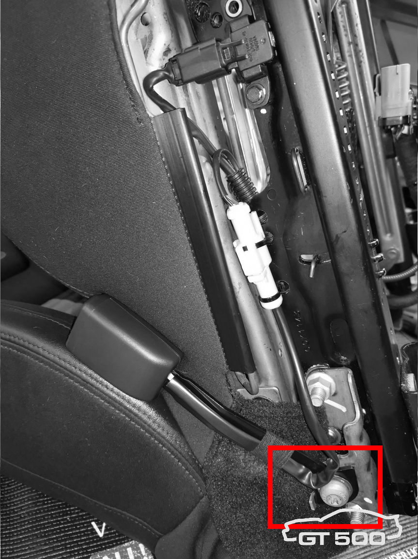
Step c. Disconnect the black seat belt electrical connector. Step d. Slide the harness-side part of the connector from the white clip. Leave the clip on the seat (the ’13 already has one). |
 |
Step e. Remove the seat belt assembly with a Torx 50. |
 |
Step f. Take the ’07 seat belt bucket assembly and bolt it on. Torque it to factory specifications. |
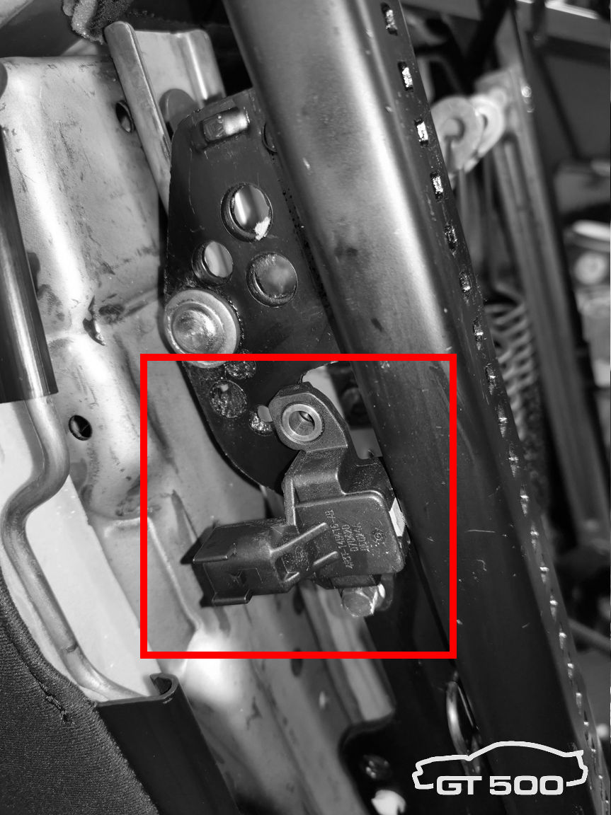 |
Step g. From here on, your situation might be different from mine. My ’13 seat didn’t have a harness left. If you have a ’13 harness, completely remove it. Leave the position sensor on the seat. |
|
Step h. Take the ’07 grey connector and have approx. 3 feet green, black and brown wire. Solder these to the corresponding colors on all ’07 connectors. Always use solder wire which is meant to use for electronics. 60% Sn / 40% Pb with a resin core. Or use a leadfree alternative. Don't use solder paste of fluid! Always use heat shrink tubing to ensure proper electrical insulation. |
|
 |
Step i. Put some cable tubing and attach the self-made harness to the seat frame. Avoid sharp edges and other possible parts that may damage the wires. Leave enough length on the harness for the seat to side. |
 |
Step j. Put the seat in the car, torque it to factory specifications, connect the grey and yellow connector and bolt it on. |
| Step k. Connect the car battery. | |
| Step l. Switch on ignition and check dash lights. In case of any doubt, switch the ignition off, disconnect the car battery, remove the seat and check for problems. | |
| Step m. If OK, check functionality by taking a short drive. Check the seat belt chime and warning lights. Always be careful. If possible, have someone check your ODB2 system for error codes related to the airbag, SRS or other safety systems. DO NOT DRIVE WHEN WARNING LIGHTS ARE LIT! |